Click
image to enlarge
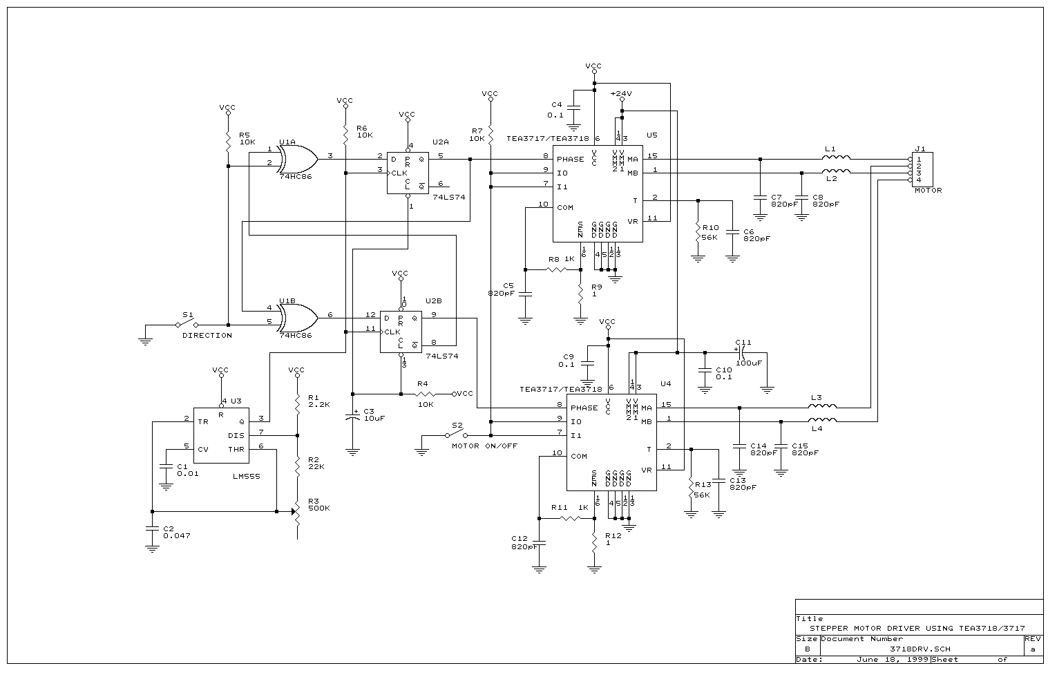
The stepper motor driver circuit is using a pair of
TEA3718/3717
to drive the stepper motor in bipolar chopper configuration. The U3 555 timer
provides the clock pulse. The U1 and U2 form a two-direction TTL full step generator. If
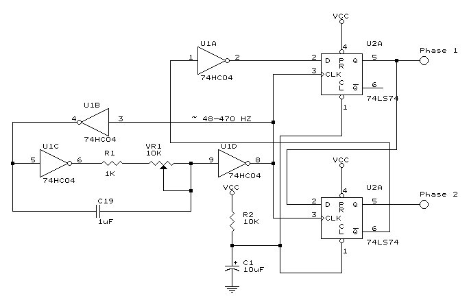
only one direction is needed then the circuit below can be used.

Figure 1
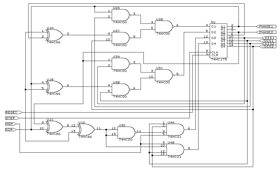
An extended TTL generator, which can generate control
signals for full step and half step is shown in Figure 2.

Figure2.
Extended TTL Generator
Click image to enlarge
Stepper Motor driver data
sheets: