For additional
information and resources on PWM DC motor drivers see the
Links
below...

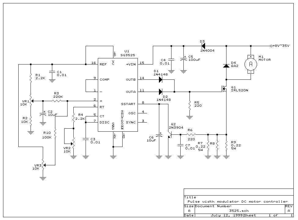
This PWM DC Motor driver circuit is ideal for the accurate control of DC motors as
well as other applications like lighting levels and small heaters etc. The
circuit converts a DC voltage into series of pulses, such that the pulse
duration is directly proportion to the value of the DC voltage. The great
advantage of such a circuit is that almost no power is lost in the control
circuit.
This PWM DC motor driver circuit protects against overload and short circuit,
SG3525 PWM range can be
adjusted from 0-100%, PWM frequency is 100HZ-5KHZ adjustable. Operation
voltage from +8V~ 35V, minimum current consumption is about 35mA. Maximum
current can go up to 6.5A. Efficiency better than 90% at full load.
The functions of three trim pots are as follow:
 |
VR1: setting the minimum output
voltage |
 |
VR3: setting the maximum output
voltage |
 |
VR2: setting the output
frequency. |
For additional
information and resources on DC motor drivers see the
Links
below...
All the parts in this project can be purchased from us. If you need help
or have any comments on this project, please email us at
info@wzmicro.com
 Back to Projects Page
View other projects:
View

Motor Driver Boards
|
Z80 Boards
|
Motor
Integrated Circuits
|
Passive components |
Miscellaneous |
RF transmitter/Receiver
| CCD Camera / Module